 In the early 20th century, a bell signalling system was used Underground in the coal mines. The bell was connected by two unprotected wires to a Leclanché cell (battery), In order to signal down the tunnel the miner would short the wires with his spade, completing the circuit and ringing the bell.
In the aftermath of a major explosion at the Senghenydd Colliery (Wales) in 1913, caused by the signalling system, it was realised that by reducing the size of the Leclanché cell i.e. reducing the voltage and current capability, sparking no longer occurred.
The applications for this were limited to low power battery systems until the development of semiconductors in the 1960s when the concept of intrinsic safety was developed.
Ex i EN 60079-11 Explosive atmospheres. Equipment protection by intrinsic safety "i"
Based on the concept of removing the ignition source by reducing the power in the circuit i.e. keeping voltage and current below the ignition level of the hazard it is the 'safest' form of protection.1
With one exception2 Intrinsic Safety is the method used for Category 1G i.e. Zone 0.
A circuit in which any spark or any thermal effect produced in the conditions specified in IEC 60079‑11, including normal operation and specified fault conditions, are not capable of causing ignition of a given explosive gas atmosphere.
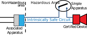
Unlike all other protection methods, for installed systems intrinsic safety is a system concept, not just an individual entity but a combination of interconnected entities.
Assuming a device is not self-contained i.e. portable then there will be at least two items (plus cable) to form an intrinsically safe circuit commonly referred to as a IS loop.
Each item in the loop can be one of 4 types:
-
Associated Apparatus is generally thought of as a stand-alone zone barrier or isolation interface (known colloquially as the barrier) but it applies to any equipment with intrinsic safety and non-intrinsic safety terminals as the barrier may be built in to other equipment e.g. distributed I/O cards or output from an alternatively protected Hazardous area device such as a thermocouple connected to an Ex d transmitter.Electrical apparatus which contains both intrinsically safe circuits and non-intrinsically safe circuits and is constructed so that the non‑ intrinsically safe circuits cannot adversely affect the intrinsically safe circuits
The Associated apparatus limits the power, voltage and current, out to the hazardous area and field equipment and does not allow for installation in the hazardous area unless another protection method3 is also used. -
Electrical component or combination of components of simple construction with well-defined electrical parameters which is compatible with the intrinsic safety of the circuit in which it is used.
 Simple apparatus does not need to be certified and consequently does not require a certification label.
However, it may require to be identified with a label so it can be easily recognised as simple apparatus rather than uncertified equipment in the hazardous area. It must also be identified in the mandatory Descriptive System Document.
A Junction box with terminals is Simple Apparatus and must be labelled as such. -
Certified Equipment
 Equipment which has an approved body type certificate (Intrinsic Safety) for Atex Category 1 & 2 or for Category 3 a competent person’s certificate e.g. by the manufacturer or other certification body4.
IECEX certification (unlike CE or UKCA) is product certification and therefore an IECEX approved certifier must be used for all Categories.
- Cables
Cables are not simple apparatus and do not require to be certified.
Intrinsic safety has a very low physical requirement for the construction and protection of cables compared with all other protection methods. The minimum is a double insulation i.e. multiple cores and outer sheath. Armour or protective sheath is not required although may be required to comply with site standards or other local site conditions to ensure segregation from non-intrinsically safe circuits.
Single cores cables are not allowed unless they are otherwise protected i.e. internally to an enclosure.
As Intrinsic Safety is a system concept the complete loop must be documented in the form of a Descriptive System Document
Internal Intrinsic Safety
Occasionally intrinsic safety is used completely internally on equipment to go into the hazardous area. The most common use is on sparking (switches) or inductive components switches to obtain a non-sparking apparatus certificate. In this case there will be no external intrinsic safety connections and it will be evident only from the equipment certification and label e.g. II 3G Ex ic nA IIC T4 Gc

Portable Equipment
Of course, Intrinsic Safety can also be used for portable equipment, the same principles apply but all part are contained in a single enclosure and the power limited within the battery assembly.
As the power comes from internal source i.e. battery, the voltage is limited by definition and the current available will be limited by a resistor or, depending on battery type and size, internal battery resistance.
If limited by an external resistor this generally should be built in the form of a failsafe assembly and encapsulation is often used.
For items using small batteries such as watches and hearing aids, the batteries inherent internal resistance may be sufficient.
Dust
Although the primary protection for dust is by enclosure Intrinsic safety is a very good method of protection as it is based on energy within the circuit. As previously shown the energy allowed for dusts is generally orders of magnitude higher than gas, although care must be taken with creepage and clearances when using conductive dusts.
Notes
-
Intrinsic Safety with 2 fault conditions i.e. Ex ia is the highest level of protection. ↩
-
The 2014 edition of EN 60074-1 introduced the concept of Ex da, (EPL 'a') Flameproof technique for Category 1G. Only Gas detection sensors equipment can be certified Ex da ↩
-
It is common for Associated apparatus to be certified Ex n or Ex ec so it can be used in within the hazardous area (Zone 2). ↩
-
An Approved body for the UK, a Notified Body for the EU or the local approval body for elsewhere. ↩